Aprilaire 1730A Specifications

Browse online or download Specifications for Dehumidifiers Aprilaire 1730A. Aprilaire 1730A Specifications User Manual

  • Download
  • Add to my manuals
  • Print
  • Page
    / 8
  • Table of contents
  • TROUBLESHOOTING
  • BOOKMARKS
  • Rated. / 5. Based on customer reviews
Page view 0
Model 1730A Compact Dehumidifier
Installation Instructions
SPECIFICATIONS
Dimensions: Width: 12.5” cabinet, 13” with doors
Height: 14.5” cabinet, 17” with 2.5” leveling feet
Length: 22” cabinet, 27” with collars
Weight: 65 lbs.
Capacity: 65 pints/day @ 150 cfm
AHAM DH-1-2003 80°F, 60% RH conditions
Efficiency: 1.8 Liters per kilowatt hour
AHAM DH-1-2003 80°F, 60% RH conditions
Power: 115VAC, 60 Hz, 8A Operating Current
Unit equipped with 8 ft. grounded power cord
Dedicated 15 Amp circuit recommended
Airflow:
Inlet Air Operating Conditions: 60°F to 95°F, 30% RH to 99% RH
Installation Conditions: 40°F to 140°F, 0% RH to 99% RH
Evaporator Frost Sensor: 25°F +/- 5°F, circuit opens (cut-out)
55°F +/- 5°F, reset temperature (cut-in)
Filter: MERV 8, washable
Dehumidistat Control Accuracy: +/- 6%RH with +/-6% Differential
WARNING
1. 120 volts may cause serious injury from electric shock. Disconnect electrical power
before starting installation. Leave power disconnected until installation is complete.
2. Sharp edges may cause serious injury from cuts. Use care when cutting plenum
openings and handling ductwork.
3. Dropping may cause personal injury or equipment damage. Handle with care.
4. Do not remove the inlet or outlet screen. Both screens are required to protect from
moving parts and electrical components.
CAUTION
1. Do not use in pool applications.
2. If unit has been shipped or stored on
its side, wait 24 hours before running.
3. Do not use solvents or cleaners on or
near the circuit board.
P ("w.c.) Airflow (cfm)
0 230
0.25 190
0.50 150
LOCATION CONSIDERATIONS
1. Install Unit Indoors: Do not expose to elements.
2. Drain Accessibility: If a drain is not located in the
installation area, a condensate pump may be required.
3. Power: Dedicated outlet within 8 feet of unit.
4. Filter Access: Allow for 12” clearance on one side of
the unit for removal of filter. (Figure 1)
5. Inlet: If inlet is not ducted, a minimum of 6” of open
space is required from the inlet panel to an adjacent
surface.
TOP VIEW
FILTER
12" MINIMUM CLEARANCE
FOR FILTER
(EITHER SIDE)
6" MINIMUM CLEARANCE
FOR PROPER AIR FLOW
90-1426
FIGURE 1 Filter
Access Clearance
UNPACKING AND CONTENTS
Do not tip unit to remove from carton.
1. Open carton completely using cut line shown along bottom
perimeter of carton.
2. Remove all cardboard inner pack (top edges and duct collars).
3. See Figure 2 for opening view and contents.
a. Installation Manual
b. Owner’s Manual
c. Dehumidistat (mounted to inlet panel)
d. Bag with Dehumidistat Cover Plate, Screws (2), Anchors (2)
e. Outlet with Back Flow Damper
f. 8 ft. Grounded Power Cord
g. Wiring Access Panel
a
b
c
d
e
f
g
FIGURE 2 Carton
Opening & Contents
90-1464
Page view 0
1 2 3 4 5 6 7 8

Summary of Contents

Page 1 - Installation Instructions

Model 1730A Compact DehumidifierInstallation InstructionsSPECIFICATIONSDimensions: Width: 12.5” cabinet, 13” with doors Height: 14.5” cabinet, 17” wi

Page 2 - MECHANICAL INSTALLATION

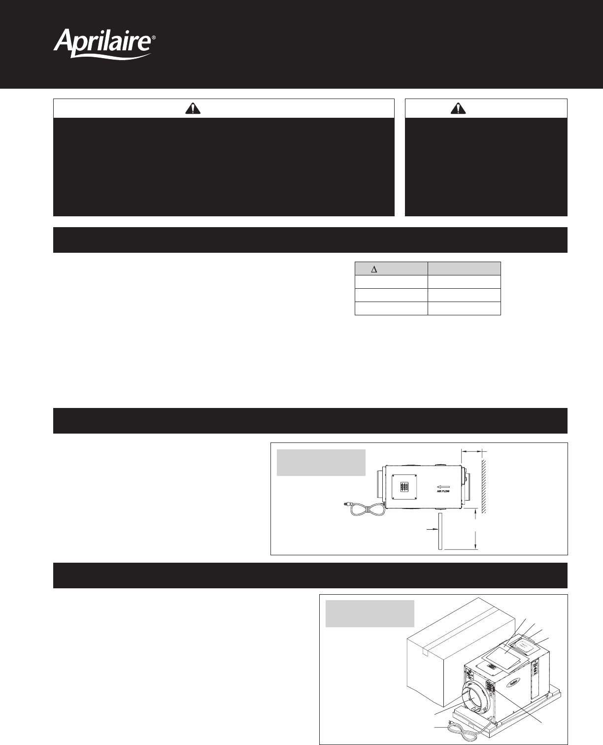
SET-UPThe dehumidifier can be installed as shipped, with the supply collar on the outlet panel, or if space is restricted, the supply collar can be re

Page 3

The dehumidifier is supplied with two 8” round collars. An integral backflow damper is installed in the outlet collar. In a ducted installation, the d

Page 4

STAND ALONE INSTALLATIONIn a free standing installation, the dehumidifier pulls air from the installed space and returns the dehumidified air back to

Page 5

KNOB ACOVER BBASE PLATE DDEHUMIDISTAT CANCHOR F (x2)SCREW E (x2)BASE PLATE DCUT WIRES4”-6” LENGTHDEHUMIDISTAT WALL MOUNT INSTALLATION (FIGURE 1

Page 6 - START UP/SYSTEM CHECKOUT

If the dehumidifier is installed in an attic or an area requiring leak protection, the unit must be placed in a drain pan with a normally closed conde

Page 7 - TROUBLESHOOTING GUIDE

SEQUENCE OF OPERATIONThe dehumidistat continually measures the humidity of the air in which it is located and controls to the dryness level set on the

Page 8 - RESEARCH PRODUCTS CORPORATION

RESEARCH PRODUCTS CORPORATIONP.O. Box 1467 • Madison, WI 53701-1467 • Phone: 608/257-8801 • Fax: 608/257-4357 • www.aprilairepartners.com10008611 6.

Comments to this Manuals

No comments