Aprilaire 8800 Universal Installation Manual
Browse online or download Installation Manual for Thermostats Aprilaire 8800 Universal. Aprilaire 8800 Universal Installation manual User Manual
- Page / 20
- Table of contents
- BOOKMARKS
Summary of Contents
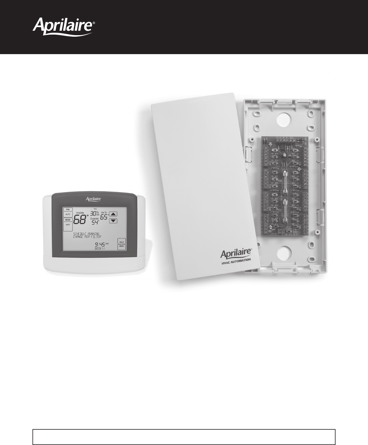
HVAC AutomationModel 8800 Communicating Thermostat System Installation ManualREAD AND SAVE THESE INSTRUCTIONS
CONNECT PROTOCOL ADAPTER TO THE DISTRIBUTION PANEL AND HOST COMPUTER OR AUTOMATION SYSTEM1. MAKE SURE THAT ALL SWITCHES ON THE DISTRIBUTION PANEL AR
CHECK-OUT HVAC SYSTEM OPERATIONUse the thermostat to verify that the equipment is being controlled. A checkout procedure is supplied in the installati
SETUP COMPUTER FOR COMMUNICATION SYSTEM CHECKOUTREQUIREMENT: HyperTerminal software and a PC with a serial port or usb to serial port adapter.1. Conn
4. This will bring up a Connect to dialog box. From the pull down next to “Connect using:”, select the Com port to which the Protocol Adapter is conn
6. From the File pull-down menu, select Properties. This will bring up a Properties dialog box.7. Select the Settings tab. Make the following
CHECK-OUT COMMUNICATIONS TO THE THERMOSTAT NETWORKThis section confirms communications to each thermostat and each thermostats network address.1. At
APPENDIX 1 – SPECIAL CONSIDERATIONS FOR INSTALLING THE MODEL 8800 WITH THE 8870 COMMUNICATING THERMOSTAT WARNINGWHEN REPLACING AN 8870 THERMOSTAT WIT
APPENDIX 2 – SENSOR AVERAGINGC BYORCRHGY2W2RT2T1S1S2WB+A+ A-B-RSARSBC BYORCRHGY2W2RT2T1S1S2WB+A+ A-B-RSARSBS1 S2 S3S6S5S4S9S8S7T1T2RWRRWWRWWWRRRWWRRWR
COMMUNICATING THERMOSTAT SYSTEM INSTALLATION MANUAL WARNING1. 120 volts may cause serious injury from electrical shock. Disconnect electrical power
P.O. Box 1467 • Madison, WI 53701-1467 • Phone: 800/334-6011 • Fax: 608/257-4357 • www.aprilairepartners.com10009416 1.12B2205497CPrinted in U.S.A.©
COLLECT THE COMPONENTS NEEDED• Small flat head screwdriver for terminal screws (1/8” wide tip).• Medium size flat/phillips head screwdriver for comp
• Use Category-5 cable for all communication wiring.• Check and recheck to ensure connection to the proper terminals before powering up the thermost
RS-232POWERRXDTXDRS-485/422DC +9VRC24VACAutomationSystemProtocol Adapter(if needed)Distribution PanelCommunicating ThermostatCommunicating HumidistatS
TO DISTRIBUTION PANELCAT- 5WIRECAT- 5WIRECAT- 5WIRECAT- 5WIRECAT- 5WIRECAT- 5WIRECAT- 5WIRECAT- 5WIRECAT- 5WIREFill Out and Leave with System Software
CONNECT THE CONTROL WIRES TO THE HVAC/ZONE SYSTEM AND THERMOSTATSA qualified HVAC technician should perform this step to ensure proper termination.1.
CONNECT THE COMMUNICATION AND POWER WIRES TO THE DISTRIBUTION PANEL AND THERMOSTAT1. MAKE SURE THAT ALL SWITCHES ON THE DISTRIBUTION PANEL ARE OFF!
CONNECT MULTIPLE DISTRIBUTION PANELS1. MAKE SURE THAT ALL SWITCHES ON THE DISTRIBUTION PANELS ARE OFF! 2. If more than one Distribution Panel is use
More documents for Thermostats Aprilaire 8800 Universal

Related products and manuals for Thermostats Aprilaire 8800 Universal
 (13 pages)
(24 pages)
(12 pages)
(25 pages)
(32 pages)
(36 pages)
(22 pages)
(19 pages)
(32 pages)
(11 pages)
(24 pages)
(3 pages)
(13 pages)
(13 pages)
(24 pages)
(12 pages)
(25 pages)
(32 pages)
(36 pages)
(22 pages)
(19 pages)
(32 pages)
(11 pages)
(24 pages)
(3 pages)
© 2020, manymanuals.com. All rights reserved. | 1.176 s |
 Manymanuals.com
 Manymanuals.de
 Manymanuals.fr
 Manymanuals.it
 Manymanuals.pl
 Manymanuals.cz
 Manymanuals.es
 Manymanuals-pt.com
Comments to this Manuals